
 API干式阀3D模型,SolidWorks源文件,API RP-1004标准
  CAD2D3D 官网服务器所有文件资源,3D模型、设计软件和案例视频等
 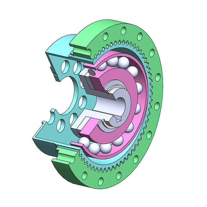 谐波减速机3D模型SolidWorks源文件下载,含stp通用格式
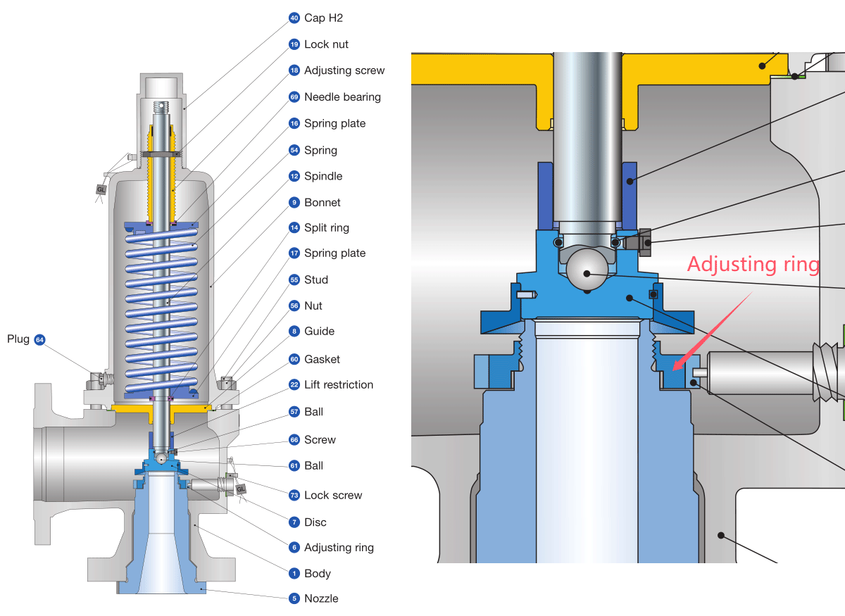
 很多厂家的安全阀上都有一个或两个调整环,调整环可以上下移动,用来调整喷嘴出口处介质对阀芯的推力,在安全阀开启后,使阀门处在一个平衡位置,避免出现上下跳动。

德国莱斯安全阀对安全阀调整环做了如下说明。
2.8 Adjusting Ring and Ringless Designs
Codes and standards specify limits for the overpressure and blowdown of safety valves. In some designs adjusting rings are used to adjust the overpressure and blowdown of the safety valve in order to meet the requirements of codes and standards. In many of them a 10% accumulation pressure is used as a basis for the design strength calculation of a pressure vessel. Therefore the overpressure for safety valves is limited to 10% of the set pressure for the majority of the applications.
Overpressure(超压排放压力):
For steam and gas applications the max. overpressure varies between 3% and 10% depending on applicable code and application. For liquids most codes specify a maximum overpressure of 10%.
Blowdown(回座压力):
Typical values for the blowdown are 4% to 15% for steam and gas and 20% to unlimited for liquids.See tables 2.8.4-1 and 2.8.4-2
2.8.1 Ringless Designs
Precise machining within narrow tolerances of all flow relevant components allow to meet code requirements without any blowdown adjustments on the valve. Safety valves without adjustment options are called fixed blowdown valves. Safety valves of this type are very common in Europe.
2.8.2 Designs with One Adjusting Ring
In the USA the majority of flanged valves are equipped with one or two adjusting rings, positioned around the nozzle and/or the disc. The position of these rings is usually factory set to meet overpressure and blowdown requirements of the applicable codes. The position of the rings can be adjusted to fine tune overpressure and blowdown of the valve. (在美国,大多数法兰阀都配有一个或两个调节环,位于喷嘴和/或阀盘周围。这些环的位置通常在出厂时设置,以满足适用规范的超压和排放要求。可以调整环的位置,以微调阀门的超压和排放。)
Designs with one ring are typically used for ASME VIII pressure vessel applications in the process industry. These designs are in most cases safety valves built according to the API 526 Standard, which shows a design containing a lower adjusting ring (API 520-1 figure 2). It is however not required to have an adjusting ring to meet ASME XIII requirements (see also section2.8.4).
For the most common design with one lower adjusting ring, changing the ring position has the following effects:
- Lowering ring: overpressure increases, blowdown decreases
- Rising ring: overpressure decreases, blowdown increases
According to LESER’s experience a significant change in the operating characteristic can only be achieved when the adjusting ring position is close to the disc and the ring almost touches the disc.(根据莱斯的经验,只有当调节环位置靠近圆盘并且调节环几乎接触圆盘时,才能实现特性的显著变化。)
Manufacturer’s instructions however do not provide information on how to adjust to specific values based on charts or tables. The effect of changed ring positions must be tested on suitable test benches that allow to measure overpressure and blowdown.
Ring adjustment should only be performed by authorized personnel and according to manufacturer’s instructions. Otherwise the operation of the safety valve in accordance with code limitations may not be guaranteed anymore.(调节环的调整只能由授权人员按照制造商的说明进行。否则,可能无法保证安全阀按照规范限制运行。)

Figure 2.8.2-1: Blowdown ring and ringless design
2.8.3 Designs with Two Adjusting Rings
Designs with two rings are typically used for ASME I steam boiler applications in order to fulfill the stringent requirements for overpressure and blowdown.(两个调整环的设计通常应用在ASME I 蒸汽锅炉,以满足超压和排放的严格要求。)

Figure 2.8.3-1: Typical ASME I safety valve design with two adjusting rings
2.8.4 Adjusting Ring at LESER
The LESER API Series 526 is the only safety valve in LESER’s product range that is equipped with an adjusting ring, following the requirements of the API 520 and API 526 standard. LESER公司只有 LESER API Series 526 产品系列根据 API520 和 API 526 标准配置了调节环。
The adjusting ring in Series 526 should be turned to the lowest possible position on the nozzle to ensure all code requirements are met. No further ring adjustment depending on set pressure or medium is required.(526 系列中的调节环应转动到喷嘴上尽可能低的位置,以确保满足所有规范要求。无需根据设定的压力或介质进行进一步的环调整。)
The benefit for the user is the easier maintenance, because no complicated ring adjustment is required.
The same applies to all other LESER designs which are ringless designs. These designs still meet all requirements of the ASME XIII, PED 2014/68/EU and other worldwide codes and standards without any change of components. This means that even if there is no requirement for the blowdown acc. to ASME XIII for ringless designs, the ringless valve types like 441 or 459 still have certified values for the blowdown. Thus, exactly the same valve types meet the most stringent requirements of ISO 4126-1 and AD 2000 A2.
The tables below show the overpressure and blowdown requirements of ASME XIII, ISO 4126-1 and AD 2000 A2 and the actual values for selected LESER safety valve types. These actual values are met independently from the code applicable to an individual order. In other words, e.g a LESER type 441 with UV stamp acc. to ASME XIII will be fully open at 5% on a steam/gas application with a blowdown of 10%.
For the LESER API Series 526 it is possible to completely leave out the adjusting ring including the lock screw. Series 526 still meets the below certified values for overpressure and blowdown. This ringless design is certified according to ASME XIII within a separate certification and is part of the CE certification as an optional version.

以下内容来自四川长仪油气集输设备股份有限公司 弹簧式安全阀使用说明书。
安全阀性能调整指导
安全阀按标准规定在常温下进行出厂试验,而安全阀实际工况和常温整定调压存在温差,故而造成常温定压和实际工况两者之间整定压力(开启压力)的偏差。为此对具有较大温差的安全阀必须进行热态调压。其调整的内容一般分整定压力(开启压力)的调整和排放与回座压力的调整。下面以我单位的两种产品(见图 5,图 6)为例作详细描述。

1. 整定压力(开启压力)的调整
打开上铅封,拆去提升架卸下阀帽,松开锁紧螺母,在弹簧规定的工作压力范围内,旋转调节螺套改变弹簧的预紧压缩量,对开启压力进行调整。调整时先缓慢升高阀进口压力,使阀门起跳一次,若开启压力偏低,卸去阀门进口压力,按顺时针方向旋紧调节螺套,若开启压力偏高,则按逆时针方向旋松之,当调整到所需的开启压力后,将锁紧螺母并紧装好阀帽,若所要求的开启压力超出弹簧所规定的工作压力范围,则需更换另一根不同工作压力级的弹簧,然后重新进行调整。在调换弹簧后,应改变铭牌上的相应数据。
调整整定压力应注意下列各项:
(1) 在调整前应将阀门内腔清洗干净,并使用清洁介质调试。
(2)当阀前压力接近开启压力(即超过开启压力的 80%)时,不能旋转调节螺套,以防阀瓣旋转,损伤密封面。
(3)在条件许可情况下,应尽可能采用与实际工作条件相接近的介质参数进行调整以保证开启压力值的准确性。若不可能采用与实际工作条件相同的介质调整开启压力时,则气体或蒸汽用安全阀可使用空气介质调整整定压力;液体或水用安全阀,可用常温水调整,当实际所使用介质温度与调整时介质的温度相差较大时,应考虑温度补偿。
(4)调整整定压力用压力表应定期校验,其精度不低于一级,定压压力值应在压力表量程的三分之一至三分之二的范围内,表盘直径应大于等于 100 毫米。
2. 排放压力和回座压力的调整
(1)对开启压力已调整好的安全阀,若排放压力或回座压力不符合要求,则可利用改变调节圈的位置来调整,安全阀结构有单调节圈和双调节圈之分(见图 5,图 6)。调整步骤是先打开下铅封,拧松调节圈紧定螺钉,然后用细铁棒之类工具,从螺孔中伸进便可拔动调节圈齿轮。若安全阀出口无连接管也可直接从出口处伸入细铁棒进行调整。为了安全起见在调整前,应使阀进口压力适当降低(一般应低于开启压力的 80%),以防止在调整时阀门突然开启,发生事故。
(2)每次调整时调节圈旋转的幅度不宜过大,一般以 2-5 齿为宜,调整结束后应随即将调节圈紧定螺钉拧紧,并使螺钉的端部位于调节圈两齿之间的凹槽内,以防止调节圈的松动。
(3)对有上、下调节圈的安全阀,一般先调整下调节圈,使排放压力达到预定值,后调整上调节圈,调试时可能出现相互干扰现象,应反复调整直到满意为止。
当逆时针方向旋转下调节圈时,其位置上升,排放压力降低,而回座压力也有所下降;反之,当顺时针方向旋转时,其位置下降,排放压力上升,但回座压力也随之略有增加。
上调节圈逆时针旋转时,其位置上升,回座压力升高,排放压力略有升高,反之,当上调节圈位置下调时,能帮助安全阀阀瓣开启,其回座压力降低,排放压力也有所降低。
(4)调整排放压力与回座压力用的试验台应有足够大的气源流量,以保证阀门达到全开启时(即达到安全阀的全开高度时)才可以测试,否则所测得的排放压力,回座压力数值是不真实的。
(5)调整后的上、下调节圈之间的相对位置不能靠得过于接近,否则会影响阀的排量。
一般情况下,上下调节圈之间的环形面积应不小于阀座喉部的截面积。
(6)调试过程中应避免出现不正常的动作,如频跳、颤振等,以防止损坏密封面。
参考文献:
- https://www.leser.com/-/media/Files/Engineering/Chapters/LID_DE_175702_EN_EHB_02_Design_Fundamentals
- 四川长仪油气集输设备股份有限公司 弹簧式安全阀使用说明书
未完待续 ~
输入暗号阅读全文
暗号:
暗号获取方式
关注微信公众号 喜爱的CAD,私信回复以下关键字:
2157暗号
即可自动获取暗号,输入的候别忘记数字后面的暗号两个字。
手机扫描下方二维码快速关注公众号 喜爱的CAD ↓↓↓

转载请注明:
文章作者: 尚延伟 原文链接:https://www.cad2d3d.com/post-2157.html
留言说明:
如对本文有疑问,可关注微信公众号 喜爱的CAD 直接留言即可。手机扫描下方二维码直接关注 喜爱的CAD。
也可以直接发邮件给我,我的邮箱18036678070@cad2d3d.com


可能感兴趣的文章
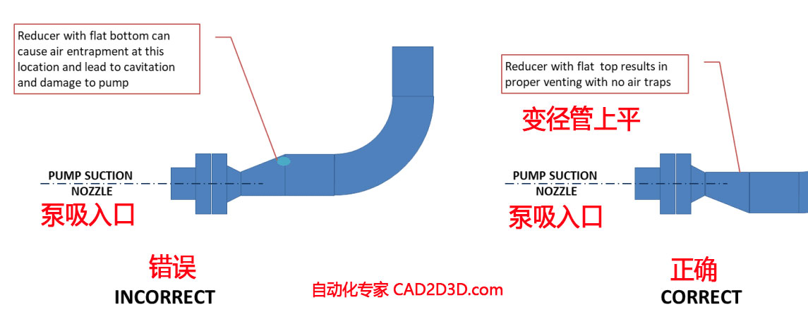 离心泵入口管道布置原则,变径管要求上平,避免入口管道内积聚气泡
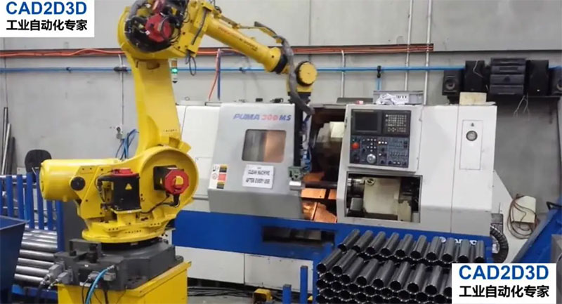 机器人给机床开关门,为什么很多人接受不了,非要给加个自动门?
更多最新发布: 化工装备
-
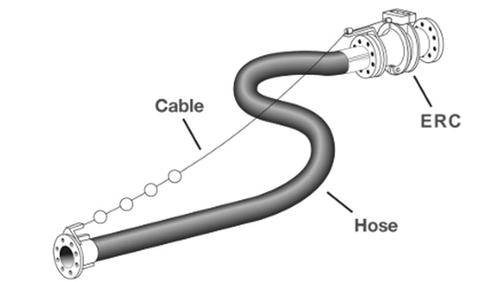 超低温拉断阀分类、内部构造和运行原理,含高清实物图、内部结构图和讲解视频
-
中间介质气化器 IFV(Intermediate Fluid Vaporizer)运行原理、内部构造和高清实物图
-
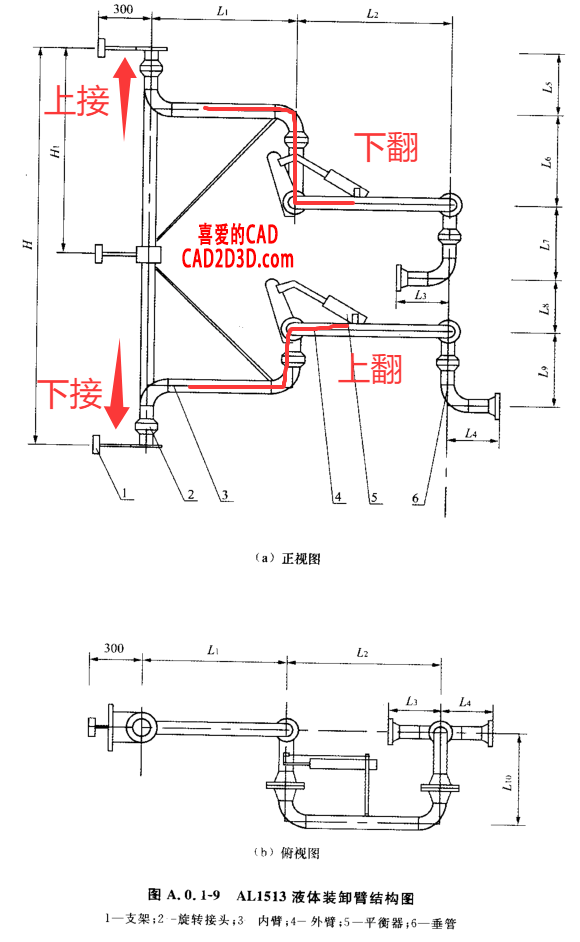 液体装卸臂(鹤管)结构形式中的上接式、下接式、上翻式、下翻式是什么意思?
-
标准中的 必须、严禁、应、不应、不得、宜、不宜、可 的用词说明
-
SH∕T 3221-2023 石油化工物料汽车装卸设施设计标准有关装卸速度(流速)的要求
-
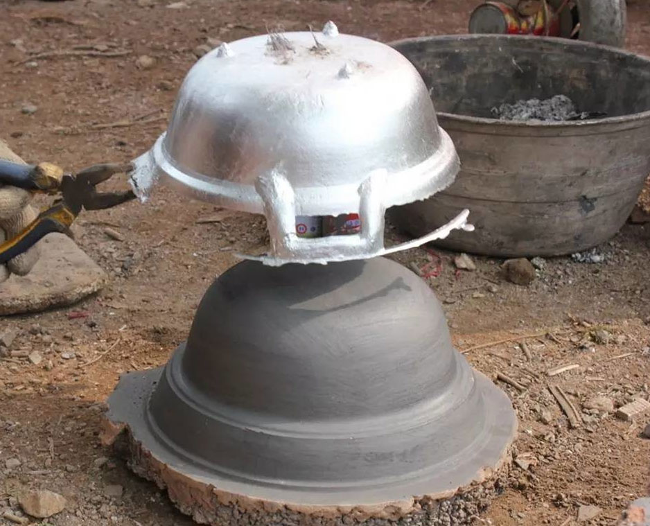 铝居然是最强金属,最低使用温度 -270 ℃,差一点就要打破绝对零度
-
GB 50093 自动化仪表工程施工及质量验收规范 温度、压力取源部件安装规定、条文解释说明及案例解析
-
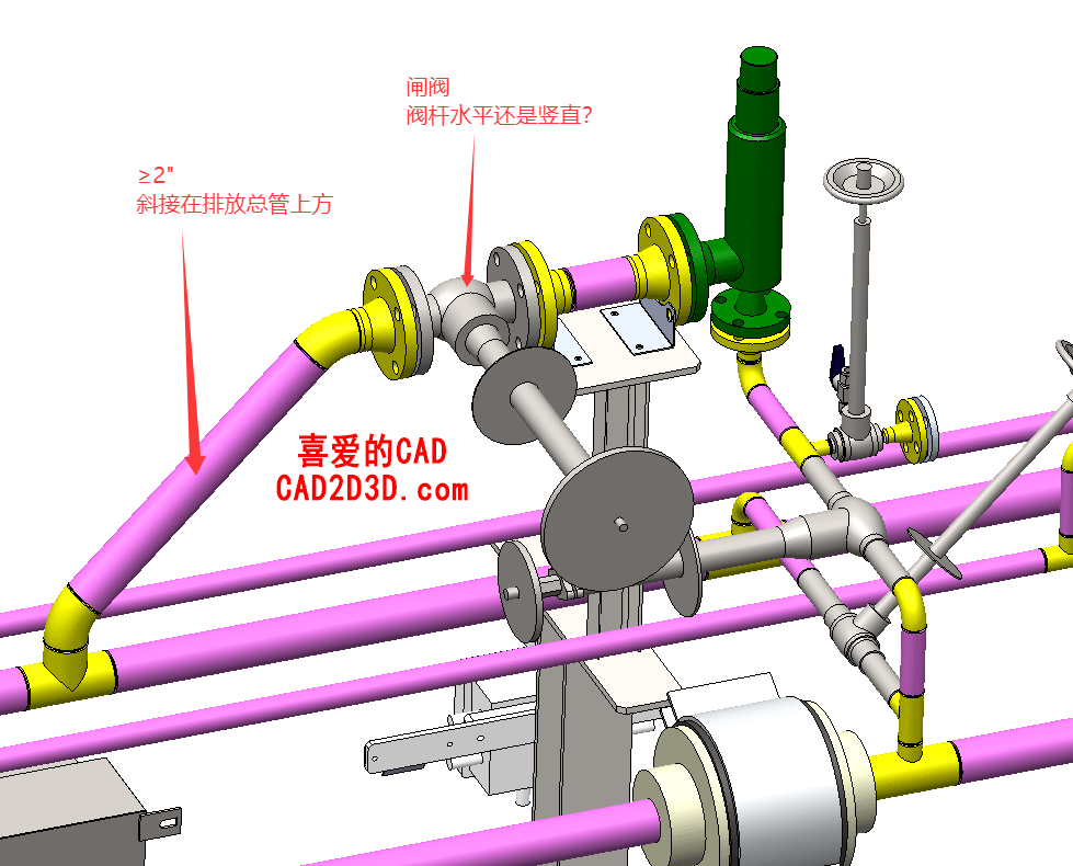 安全阀排放管低温闸阀应水平安装还是竖直安装?SH 3012 要求阀杆水平,GB/T 24925 要求阀杆与地面大于45°角安装,到底应该听谁的啊?
 本站所有资源一键获取,含3D模型、设计软件和案例视频等
 支付宝现金红包,又疯狂“大面积”送钱了!人均 1-20 元 (无套路/每天能领)
 AutoCAD 2025 破解版+注册机 安装程序免费下载,附下载地址及安装教程
 SolidWorks 2024 SP2.0 破解版免费下载及安装教程
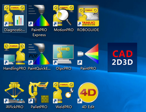 发那科机器人 FANUC 离线编程 动画仿真模拟软件 ROBOGUIDE V9 免费下载