莱斯安全阀对安全阀的安装位置说明如下:
6.2.4 Location of the Safety Valve(安全阀安装位置)
6.2.4.1 Distance to Pressure Source(距离压力源)
The safety valve should normally be placed close to the protected equipment so that the pressure losses to the safety valve are within the allowable limits. For example, where protection of a pressure vessel is involved, mounting the safety valve directly on top of the vessel is suggested. However, on installations that have pressure fluctuations at the pressure source (as with valves on the compressor discharge) that peak close to the set pressure of the safety valve, the safety valve should be located farther from the source (e.g. behind a compressed air chamber) and in a more stable pressure region.(来自:API RP 520 Part II, 5 th Edition 2003, Sect. 9.2)(安全阀通常应放置在靠近受保护设备的位置,以便安全阀的压力损失在允许的范围内。例如,当涉及保护压力容器时,建议将安全阀直接安装在容器顶部。但是,在压力源处存在压力波动的装置(如压缩机出口处的阀门)峰值接近安全阀的设定压力时,安全阀应位于离源更远的地方(例如,在压缩空气室后面)和更稳定的压力区域)
6.2.4.2 Distance to Other Valve Equipment(距离其他阀门设备的)
The safety valves should not be located where unstable flow patterns are present (Figure 6.2.4.2-1).(安全阀不应位于存在不稳定流型的地方)
The branch entrance where the safety valve inlet line joins the main piping run should have a well rounded, smooth corner that minimizes turbulence and resistance to flow.(来自 API RP 520 Part II, 5 th Edition 2003, Sect. 9.3)(安全阀入口管线与主管道连接处的支入口应有一个圆润、光滑的拐角,以最大限度地减少湍流和流动阻力。)
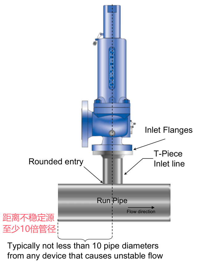
Figure 6.2.4.2-1: Distance to other valve equipment acc. to API 520 part II
6.2.4.3 Sources of Irritation(敏感源)
Safety valves are often used to protect piping downstream from pressure reducing valves or control valves, where unstable flow usually occurs. Other valves and equipment in the system may also disturb the flow. This condition cannot be evaluated readily, but unsteady flow at valve inlets tends to generate instability. Therefore safety valves should be installed at least 10 pipe diameters away from the source of irritation.(来自 API RP 520 Part II, 5 th Edition 2003, Sect. 9.3.1)(安全阀通常用于保护下游管道免受减压阀或控制阀的影响,这些减压阀或控制阀通常会出现不稳定的流量。系统中的其他阀门和设备也可能干扰流动。这种情况无法轻松评估,但阀门入口处的不稳定流动往往会产生不稳定。因此,安全阀应安装在距离刺激源至少 10 个管径的地方。)
The proximity to orifice plates and flow nozzles may cause adverse performance of the safety valves. Also the use of other fittings, such as elbows, may create turbulent areas that could have an impact on the safety valve’s performance.(API RP 520 Part II, 5 th Edition 2003, Sect. 9.3.2)(靠近孔板和流量喷嘴可能会导致安全阀性能不佳。此外,使用其他配件,如弯头,可能会产生湍流区域,从而影响安全阀的性能。)
6.2.4.4 Process Laterals Connected to the Inlet Line of Safety Valves(工艺管道不应连接到安全阀入口管线上)
“Process laterals should generally not be connected to the inlet line of safety valves. Exceptions should be analyzed carefully to ensure that the allowable pressure loss at the inlet of the safety valve is not exceeded under simultaneous conditions of rated flow through the safety valve and maximum possible flow through the process lateral (Figure 6.2.4.4-1).(来自 API RP 520 Part II, 5 th Edition 2003, Sect. 4.7)
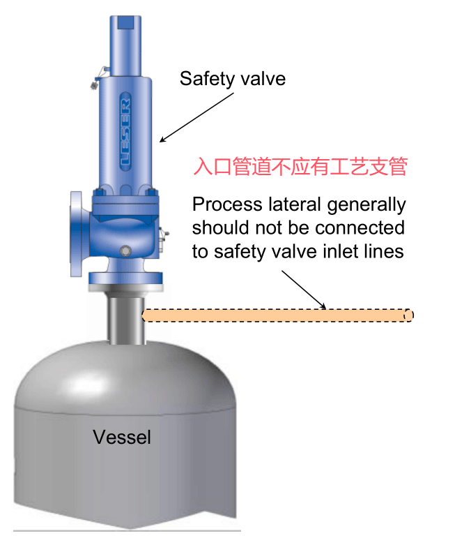
Figure 6.2.4.4-1: Process lateral acc. to API 520 part II
6.3 Plant Design – Inlet Line(入口管线)
Within this section requirements regarding the inlet line of safety valves within the specific plant design are characterized. Several codes and standards deal with this subject and have very similar conclusions. API 520 Part II is very detailed with its description and is the basis for the statements in this section. In cases where other codes and standards differ from statements in API 520 Part II,
these differences will be explained. Other referenced codes and standards are:
- DIN EN ISO 4126-9
- AD 2000-Merkblatt A2
- ASME Section VIII Division 1
6.3.1 Correct Sizing of the Inlet Line(入口管线尺寸)
To size and design an inlet line properly the following aspects have to be considered.(安全阀入口管线尺寸设计需要考虑以下事项)
1. The pressure loss shall not exceed 3%. The following measures help to fulfill this requirement(压力损失不得超过 3%。以下措施有助于满足此要求):
- The inlet line should be as short and straight as possible(入口管线应尽可能短而直)
- Nominal pipe diameter equal or larger than valve inlet size(入口管线公称直径等于或大于阀门入口尺寸)
- Rounded edges at the entrance to the inlet line(入口管路入口处的圆角边缘)
2. Stress should be avoided.(避免附加应力)
3. Vibrations in the inlet line should be avoided.(避免入口管线震动)
4. The inlet line should be free-draining(入口管线应为自由排水管路)
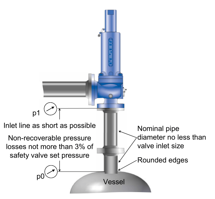
Figure 6.3.1-1: General guidelines for inlet lines
6.3.2.1 Unfavourable Size, Length and Configuration of Inlet Lines(入口管线不应该这样设置)
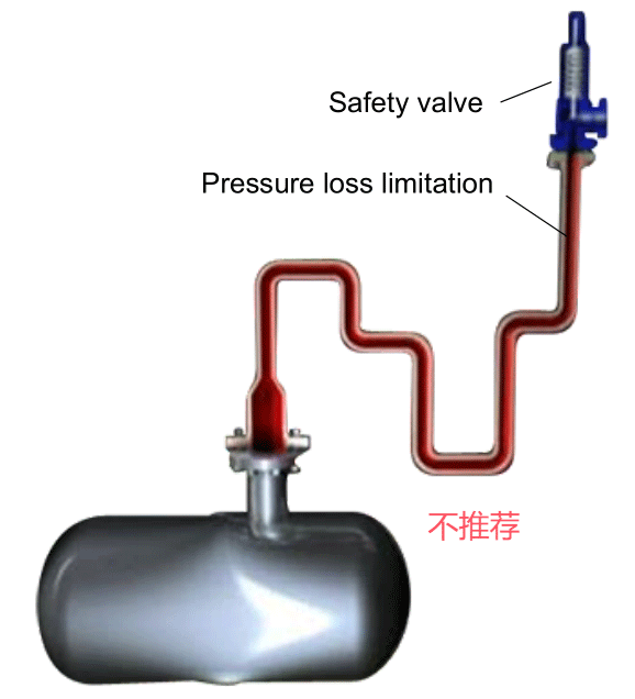
Figure 6.3.2.1-1: Incorrect sizing of inlet line
Incorrect sizing can cause excessive pressure loss. The following configurations are unfavourable(尺寸不正确会导致压力损失过大。以下配置是不利的):
- Long inlet line with several bends, elbows or other equipment installed before the safety valve(在安全阀之前安装多个折弯、弯头或其他设备的长入口管线)
- Too small inlet line size(入口管线尺寸太小)
- Sharp edges at the entrance to the inlet line(入口管路入口处的锋利边缘)
参考文献:https://www.leser.com/-/media/Files/Engineering/Chapters/LID_DE_175706_EN_EHB_06_Installation%20and%20plant%20design
 精密橡胶模具导柱导套硅胶密封圈模导柱自动化定位柱定位销F1F2型
  电脑游戏办公自动化工具软件鼠标键盘连点器脚本编辑录制同步后台
  F3型精密橡胶模精定位工装夹具定位销模具导柱导套自动化定位柱
 作者:尚延伟
转载请注明:
文章作者:尚延伟,原文链接:https://www.cad2d3d.com/post-2159.html
留言说明:
如对本文有疑问,可关注微信公众号 喜爱的CAD 直接留言即可。手机扫描下方二维码直接关注 喜爱的CAD。

也可以直接发邮件给我,我的邮箱18036678070@cad2d3d.com



可能感兴趣的文章
- 清华大学本科生期望薪资月入过万,是高还是低?
- 美国 吉尔巴克-维德路特 VEEDER 官网,GVR、加油机、红夹克潜油泵和长吉加油机
 桁架机械手安装调试太难了,精度要求那么高,我们根本干不了
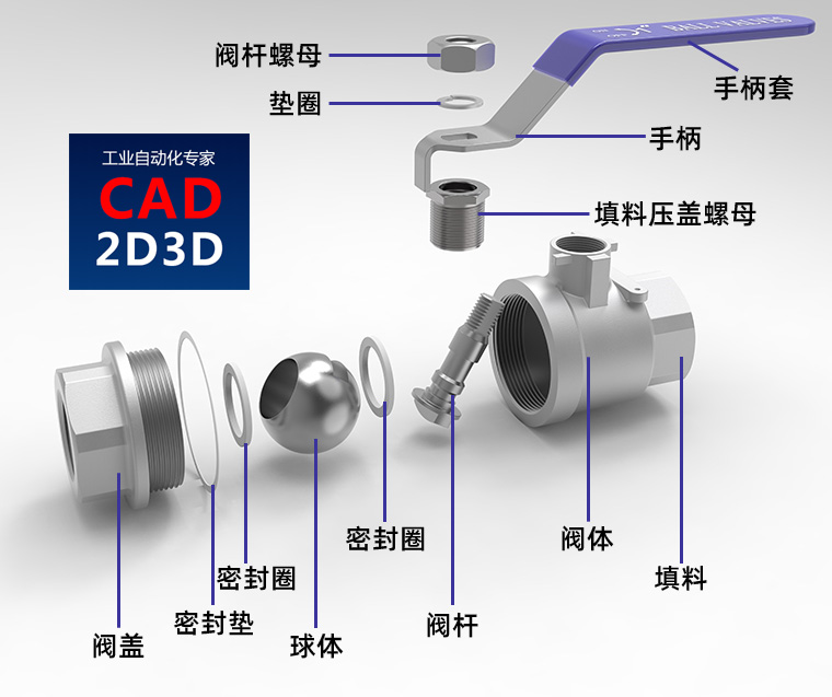 一片式球阀、两片式球阀、三片式球阀和广式球阀的内部构造和区别
- 瑞士史陶比尔(Staubli)官网,专注工业连接器、工业机器人和纺织机械工业自动化
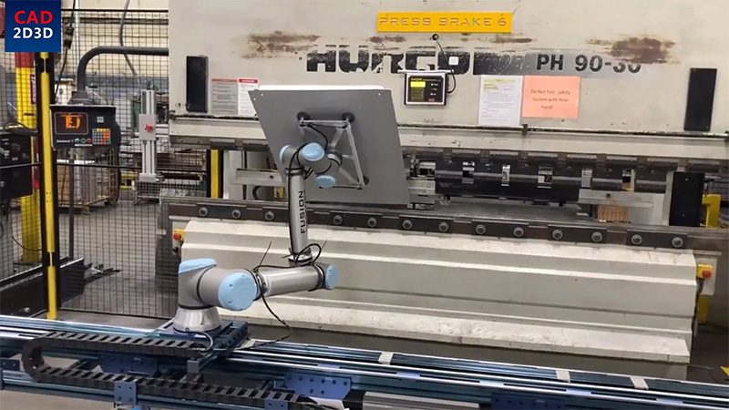 国外设计的机器人折弯生产线
- 磁力吸盘开合原理,为什么底部要开V型槽?
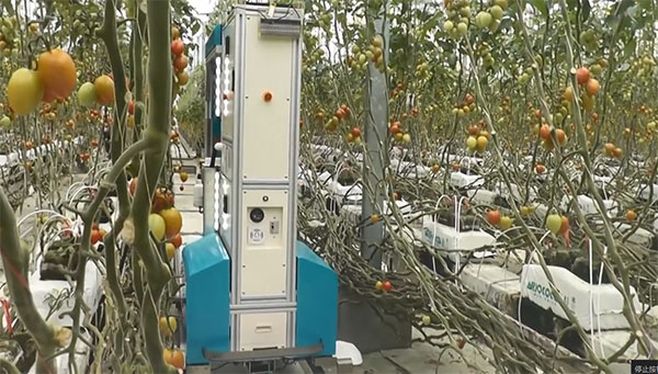 番茄自动化采摘AI机器人 视觉识别技术实际应用
- 生产制造各工序图标标识免费下载
 儿童安全防护锁 直接粘在门上 可用于抽屉、冰箱门
 平顶链(链板)输送机结构原理(图)
- 视觉相机图像识别处理配合机械手/机器人应用场景及使用方法(基恩士)
更多最新发布: 化工装备
-
 LNG装卸臂智能化对接装置的研究与设计
-
 卡套式接头连接和密封可靠吗?总感觉压力大了或时间长了它会松动
-
 超低温拉断阀分类、内部构造和运行原理,含高清实物图、内部结构图和讲解视频
-
中间介质气化器 IFV(Intermediate Fluid Vaporizer)运行原理、内部构造和高清实物图
-
 液体装卸臂(鹤管)结构形式中的上接式、下接式、上翻式、下翻式是什么意思?
-
标准中的 必须、严禁、应、不应、不得、宜、不宜、可 的用词说明
-
SH∕T 3221-2023 石油化工物料汽车装卸设施设计标准有关装卸速度(流速)的要求
-
 铝居然是最强金属,最低使用温度 -270 ℃,差一点就要打破绝对零度
-
GB 50093 自动化仪表工程施工及质量验收规范 温度、压力取源部件安装规定、条文解释说明及案例解析
-
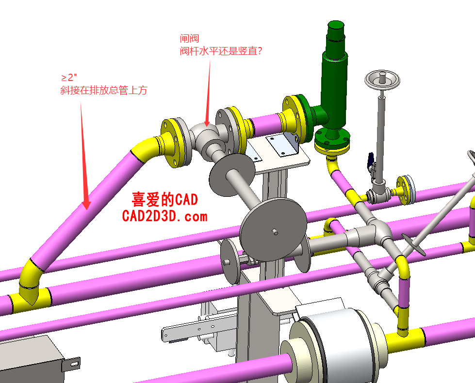 安全阀排放管低温闸阀应水平安装还是竖直安装?SH 3012 要求阀杆水平,GB/T 24925 要求阀杆与地面大于45°角安装,到底应该听谁的啊?
-
电气装置应接地,螺栓应有防松装置,接线端子及紧固件应涂电力复合脂
-
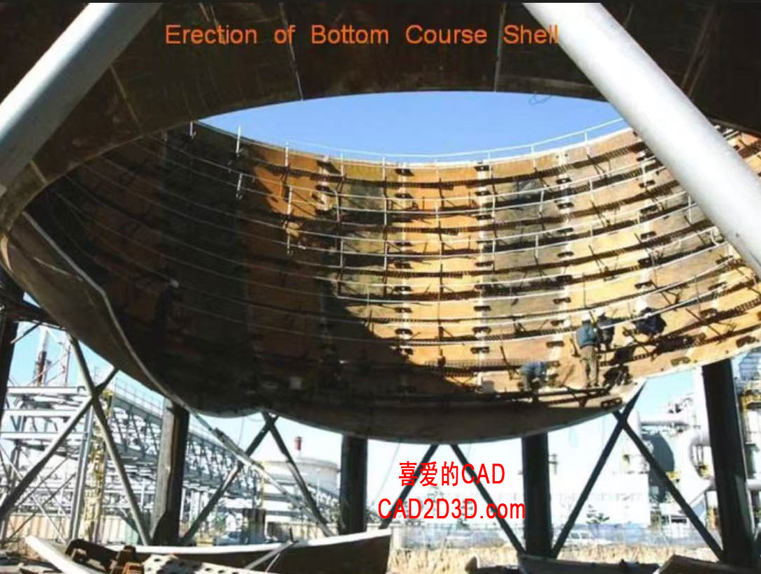 钢厂作业人员必备!饱和水蒸气球罐(球形蒸汽蓄热器)技术参数、生产制造过程、实物图及潜在失效模式分析
 本站所有资源一键获取,含3D模型、设计软件和案例视频等
 支付宝现金红包,又疯狂“大面积”送钱了!人均 1-20 元 (无套路/每天能领)
 《工业机器人系统集成&自动化生产线方案设计大师》第2版免费送,机器人及自动化技术人员必备教材
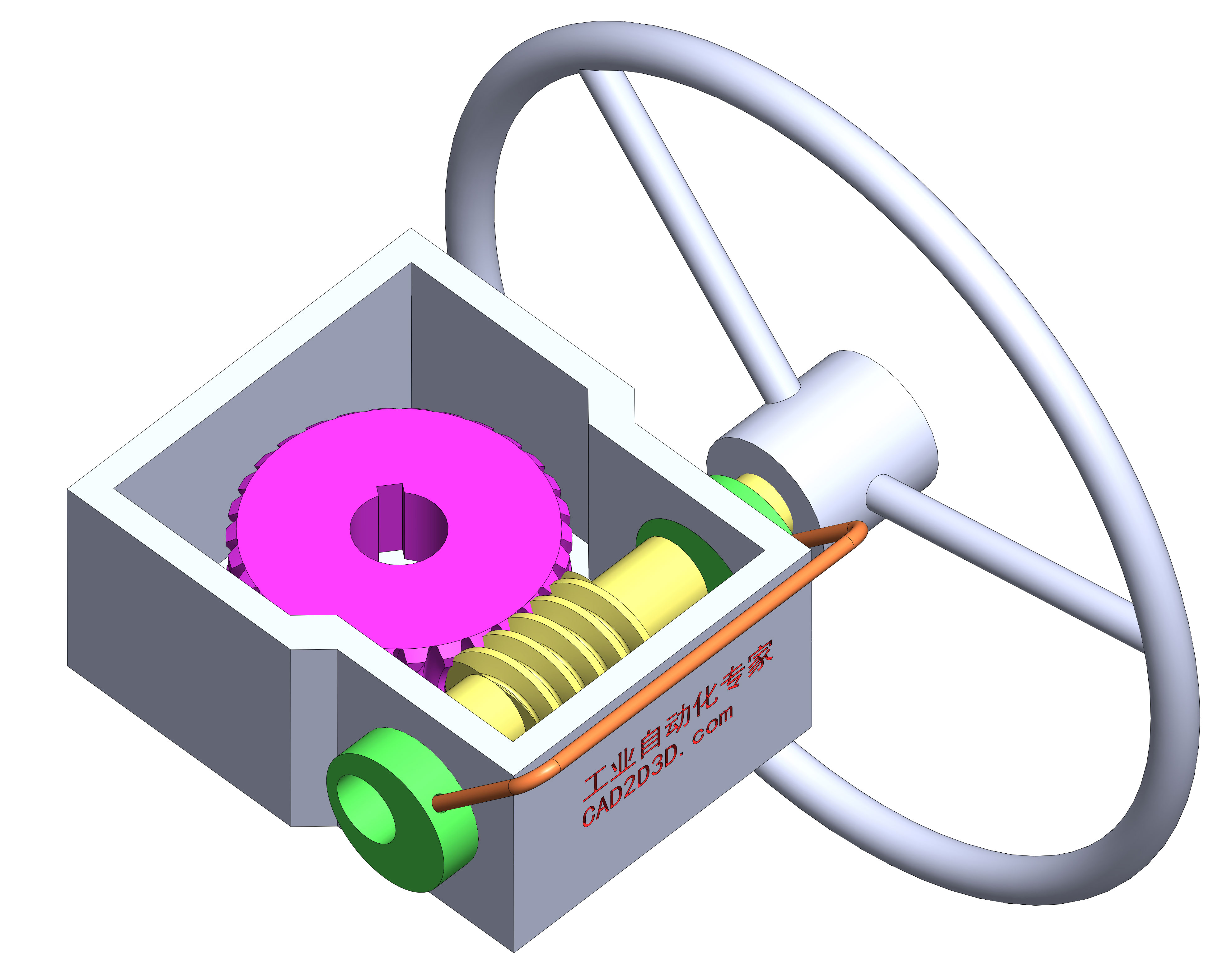 气动控制阀手动操作机构内部构造,手动自动切换原理,含视频演示及免费三维模型
 《装车橇设计大师》教材发布,压力元件组合装置设计,石油化工行业技术人员必备
 LNG装车橇3D模型免费下载,SolidWorks源文件下载,STEP通用3D模型文件下载
 AutoCAD 2025 免费版+注册机 安装程序免费下载,附下载地址及安装教程
 SolidWorks 2024 SP2.0 免费版免费下载及安装教程
 API干式阀3D模型免费下载,SolidWorks源文件,Stp通用格式
 机械手 Z 轴行程放大机构3D模型 SolidWorks 源文件免费下载
 谐波减速机 3D 模型 SolidWorks 源文件免费下载,含 stp 通用格式,结构看似简单,实则脑洞大开
 发那科机器人 FANUC 离线编程 动画仿真模拟软件 ROBOGUIDE V9 免费下载
 公差分析(WC、RSS、6Sigma)和公差分配(权重因子、最小成本)方法及计算表格下载