
 2026新款智能机器人儿童AI人工编程早教电动遥控玩具男孩生日礼物
  2026新款ai智能机器猫狗儿童玩具人工编程电动遥控男女孩生日礼物
  Cami o1 智行版AI车载智能机器人伴驾精灵电子宠物汽车中控台摆件语音对话机器人陪伴2026新款
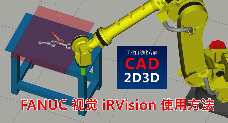
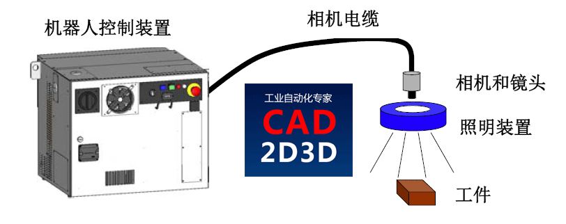
 1 FANUC iRVision 视觉概述
FANUC 机器人自带iRVision软件(不是标配,需要选装),专门用来处理视觉应用,相机介入机器人控制系统后,通过iRVision可以实现视觉的快速应用。
iRVision是一个图形化的界面,不需要编程,用户只需要配置一下相机参数和视觉处理工具就行。
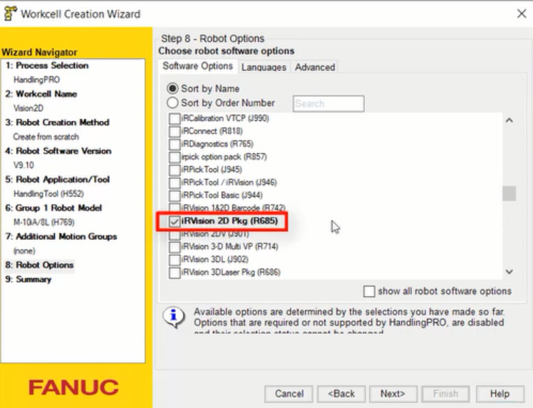
注意:使用FANUC ROBOGUIDE仿真软件进行2D视觉仿真时,需要勾选iRVision 2D Pkg (R685)选软才行,具体见下图。
2 FANUC iRVision 视觉设置界面
使用 FANUC ROBOGUIDE 仿真软件进行视觉设置的,可以点菜单栏 ROBOT/ Internet Explorer 进入,使用机器人示教器的可以点 MENU / iRVision / Vision Setup进入。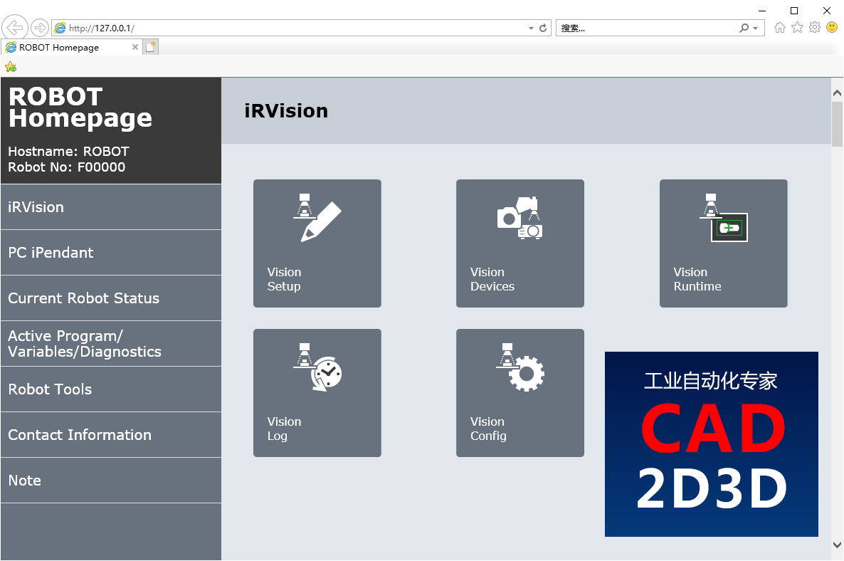
3 视觉设置(Vision Setup)
点击 Vision Setup 进入视觉设置界面,需要设置 相机数据(Camera Data)和视觉处理工具(Vision Process Tools)两项内容。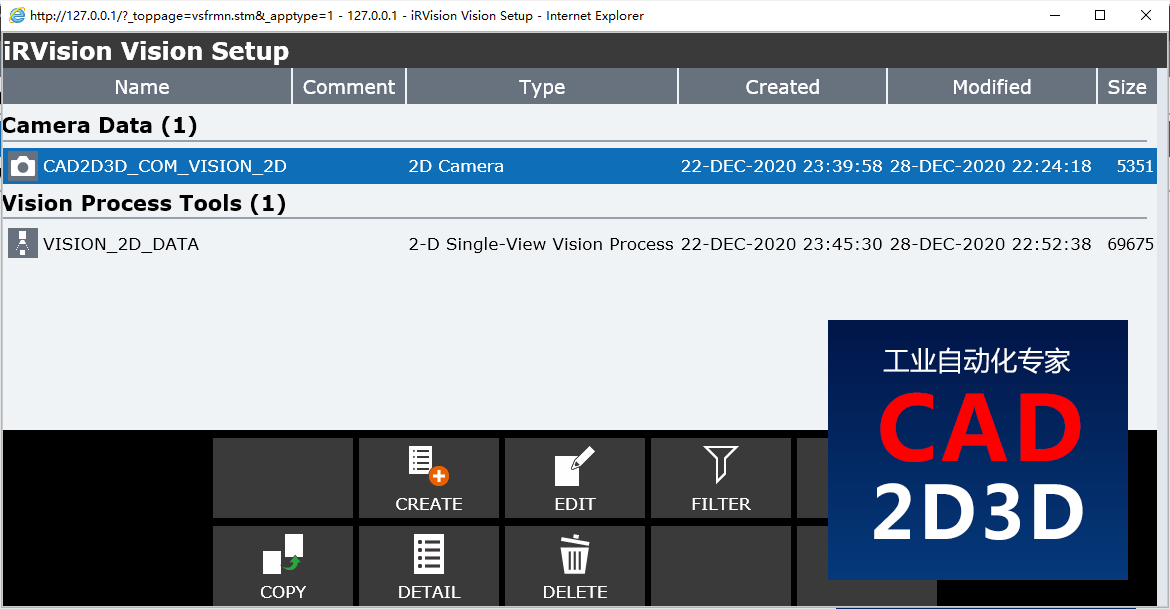
4 相机数据设置
点击CREATE新建一个相机数据文件,对相机参数进行设置,并执行相机校验标定。
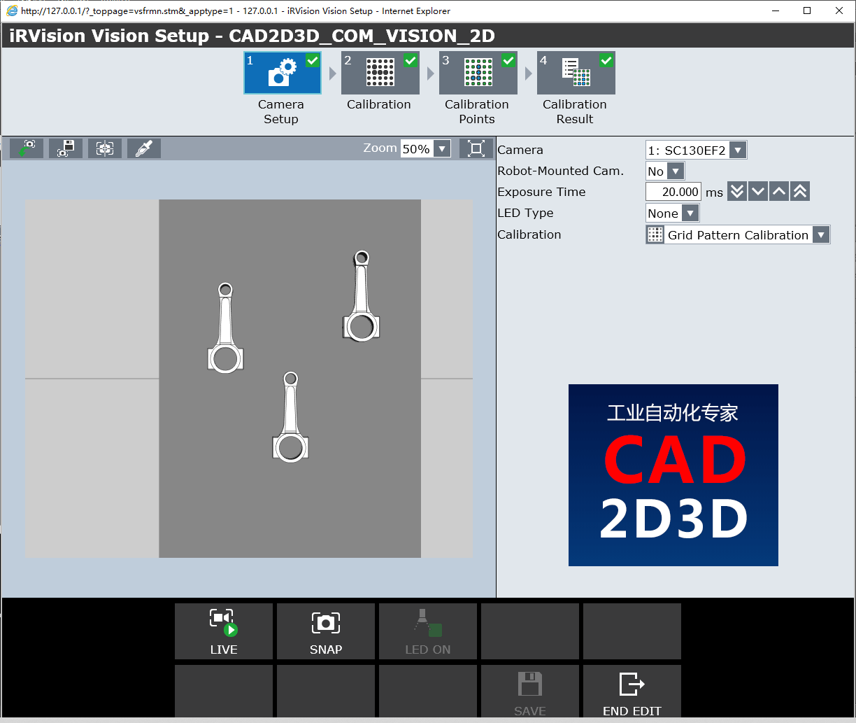
4.1 相机参数设置(Camera Setup)
- Camera:选择相机
- Robot Mounted Cam.:相机是否安装在机器人上
- Exposure Time:曝光时间
- LED Type:LED光源类型
- Calibration:校验标定类型
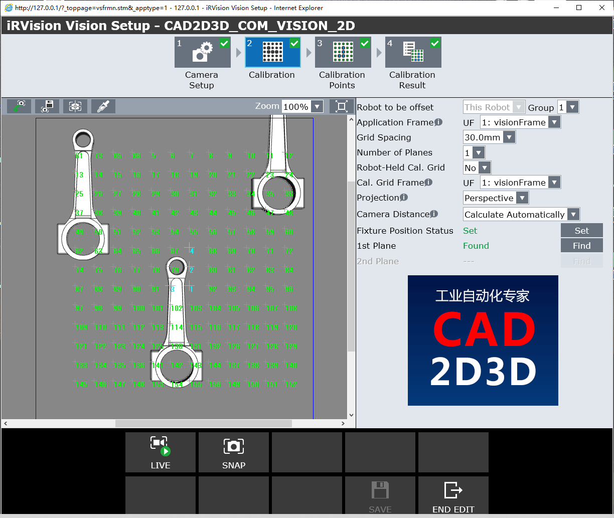
4.2 相机校验标定(Calibration)
- Robot to be offset:需要偏移的机器人
- Application Frame:应用坐标系
- Grid Spacing:标定板单元格尺寸大小
- Number of Plates:标定板数量
- Robot held Cal. Grid:机器人手持标定板
- Projection:投影方式
- Cameral Distance:相机距离
- Fixture Position Status:夹具位置状态
- 1st Plate:第一个标定板
4.2.1 应用坐标系(Application Frame)
应用坐标系属于用户坐标系,用来实现相机标定。 应用坐标系的Z方向必须大致指向相机的光轴。 如果摄像机指向上方或下方,则应用坐标系可以是世界坐标系(UFRAME [0])。
The Application Frame is one of the user frames used for camera calibration. The Z direction of this user frame must roughly point along the optical axis of the camera. If the camera is pointing up or down then the Application Frame can be World (UFRAME[0]).
大多数视觉流程都会涉及到偏移坐标系。视觉识别系统就是在此偏移坐标系内计算出实际工件的偏移量。 少数不使用“偏移坐标系”的视觉处理在“应用坐标系”中计算了工件的偏移量。
Most Vision Processes have an Offset Frame. The Offset Frame is the user frame in which the vision process offset is calculated. The few vision processes that do not use an Offset Frame, have their offset calculated in the Application Frame.
在相机朝上或朝下时,选择机器人用户坐标系UFRAME[0]作为视觉的应用坐标系,但是相机或标定板装在另一个机器人手臂上的情况除外。
You should select World (UFRAME[0])as the application frame number when the camera is pointing up or down, except when the camera or grid is mounted on a different robot arm.
如果相机不是朝上或朝下(视觉应用坐标系不能选择 UFARME[0])),通常情况下将用户坐标系设在标定板上。
If the camera is not pointing up or down (which makes World (UFARME[0]) unacceptable), then the User Frame which was taught to the calibration grid is a good choice in most applications.
4.2.2 标定板坐标系(Cal. Grid Frame)
标定板坐标系设置在标板上。
The Cal. Grid Frame is the frame that is taught to the calibration grid.机器人手持标定板 = 否
Robot Held Cal. Grid = NO
如果标定板不是机器人手持的,并且“Robot-Held Cal Gridparameter”参数设置为“No”,则标定板坐标系就是“用户坐标系”。 使用iRVision实用程序“Automatic Grid Frame Set”或使用四点方法手动教用户坐标系。 下图是使用“四点法”手动示教用户坐标系的步骤,需要机器人走4个点位,机器人控制系统通过4个指定点位自动计算出用户坐标系位置和朝向。
If the calibration grid is not held by the robot and the Robot-Held Cal Gridparameter is set to NO, then the calibration grid frame is a USER FRAME. Teach the USER FRAME using the iRVision Utility "Automatic Grid Frame Set", or manually using the Four-Point Method. The image below shows the four points that are required to teach the USER FRAME if you opt to teach the frame manually using the Four-Point Method.
- Y Direction Point (Y方向)
- System Origin (系统中心点)
- Orient Origin (坐标系原点)
- X Direction Point (X方向)
机器人手持标定板 = 是
Robot Held Cal. Grid = YES
如果机器人手持标定板, 并且 Robot-Held Cal Gridparameter设置为YES,则标定板坐标系是一个工具坐标系(TOOL FRAME),可以使用 iRVision 实用程序 Automatic Grid Frame Set设置,或采用6点法手动示教出工具坐标系。下图是6点法示教工具坐标系的步骤。
If the calibration grid is held by the robot and the Robot-Held Cal Gridparameter is set to YES, then the calibration grid frame is a TOOL FRAME. Teach the TOOL FRAME using the iRVision Utility "Automatic Grid Frame Set", or manually using the Six-Point Method (XY) or (YZ). The image below shows the six points required to teach the TOOL FRAME if you opt to teach the frame manually using the Six-Point Method.
- X Direction Point
- Appr. Points 1, 2, and 3
- Orient Origin
- Y or Z Direction Point
使用上述方法创建的工具坐标系(TOOL FRAME)X轴被旋转了90度,因此当示教完成后,必须将角度 W 手动增加90°。
The TOOL FRAME, that is set using the points shown above, creates a TOOL FRAME that is rotated by 90 degrees about the X-axis. After the frame is taught this must be corrected by manually adding 90 to the value of W.
4.2.3 投影方法(Projection)
校准标定有2种投影方法,分别是透视和正交。
There are two types of calibration projection methods, Perspective and Orthogonal.
1)透视(Perspective)
透视校准标定是默认方法,推荐使用。透视校准标定可以确定相机的高度。在知道相机和校准标定板之间的距离的情况下,可以使用相同的校准来计算不同高度的工件偏移。视觉处理时将工件的不同高度定义为Z部高度。可以通过四种方式实现正确的透视校准标定。
Perspective Calibration is the default method and nearly always the recommended choice. Perspective Calibration is able to determine the height of the camera. With the distance between the camera and the calibration grid known, the offset of workpieces at different heights can be calculated using the same calibration. The different heights of the workpieces are defined in the vision process as the Part Z Height. Proper perspective calibration can be achieved in four ways.
两平面校准 —— 对于相机固定安装的应用,将安装在机器人末端的标定板移动到摄像机下方的两个位置。对于相机安装机器人手爪上的应用,将摄像头移动到网格上方的两个位置。在相机的光轴上移动标定板或相机。
Two Plane Calibration - For a fix-mount camera application, move the robot-mounted calibration grid to two positions under the camera. For a robot-mounted camera application, move the camera to two positions above the grid. Move the grid or camera in the optical axis of the camera.倾斜平面校准 —— 将校准网格放在楔形上,使其相对于摄像机的光轴倾斜。
Tilted Plane Calibration - Place the calibration grid on a wedge so that it is tilted with respect to the optical axis of the camera.
重写焦距—— 通过输入镜头的焦距来重写焦距。镜头的焦距通常写在镜头主体上。注意:校准后,可能需要稍微调整此值,以使结果与从相机(镜头中心)到标定板的物理距离相匹配,因为焦距会随焦点调整而变化,因此可能与镜体上写的值不是完全一样。
Override Focal Dist. - Override the focal distance by entering the focal distance of the lens. The focal distance of the lens is typically written on the lens body. Note:After calibration, this value might have to be adjusted slightly so that the result matches the physical distance from the camera (center of the lens) to the grid, since the focal distance changes with focus adjustments and, therefore, might not be exactly the value written on the lens body.
重写摄像机距离 —— 通过输入从相机到标定板的距离来覆盖相机的距离。测量从相机镜头中心到标定板的距离。
Override Camera Dist. - Override the camera distance by entering the distance from the camera to the calibration grid. Measure the distance from the center of the camera lens to the calibration grid.
2)正交(Orthogonal)
正交法校验标定限定在工件在一个高度上(偏移坐标系的高度),Z方向高度定义为0。
Orthogonal Calibration is limited to workpieces at only one height, the height of the Offset Frame. The Part Z Height defined in the vision process must be zero with Orthogonal Calibration.
4.2.6 相机距离(Camera Distance)
通过计算相机高度和焦距来选择校验标定工具。
Choose how the calibration tool should calculate the standoff distance and the focal distance shown in the diagram below.
如果有多个校准平面,则别无选择。 摄像机距离线将被禁用,软件将自动计算摄像机距离。
If there are multiple calibration planes, there is no choice. The Camera Distance line will be disabled and the software will calculate the camera distances automatically.
对于单平面校准标定,如果相机倾斜10度或以上,请使用以下方法1。 否则,软件将显示一条警告消息,提示距离可能不正确, 在这种情况下,您应该使用方法3。方法2是为了与旧软件版本兼容。
For a single plane calibration, if the camera is tilted 10 degrees or more, use method 1 below. Otherwise, the software will display a warning message that the distances may be inaccurate. In this case you should use method 3. Method 2 is provided for compatibility with old software versions.
方法1. 自动计算(Calculate Automatically)
方法2. 重写焦距(Override Focal Distance)
该距离将略大于镜头上标记的焦距,并取决于镜头对焦的距离,镜头聚焦得越近,它将越大。
This distance will be slightly larger than the focal length marked on the lens and depends on what distance the lens is focused at. The closer you focus the lens, the larger it will be.
方法3. 重写相机距离(Override Standoff Distance)
测量从标定板原点到镜头中点的距离(镜头末端和相机上的螺纹开口之间的一半距离)。
Measure the distance from the calibration grid origin to the mid-point of the lens (half way between the end of the lens and the threaded opening on the camera).
4.3 标定点参数值(Calibration Points)
- Vt:图像垂直方向像素数,也就是行号(Row)
- Hz:图像水平方向像素数,也就是列号(Col)
- X:视觉坐标系中X坐标
- Y:视觉坐标系中Y坐标
- Z:视觉坐标系中Z坐标
- Err:误差

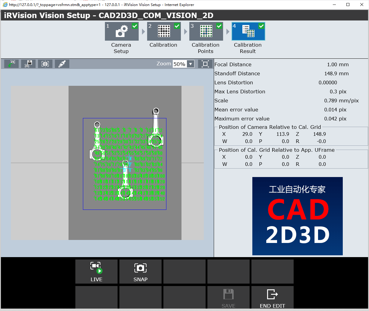
4.4 标定结果(Calibration Results)
- Focal Distance:相机镜头焦距
- Standoff Distance:相机距离
- Lens Distortion:镜头畸变
- Max Lens Distortion:镜头最大畸变
- Scale:比例
- Mean error value:平均偏差
- Maximum error value:最大偏差误差
- Position of Camera Relative to Cal.Grid:相机位置相对于标定板
- Position of Cal.Grid Relative to App. UFrame:标定板位置相对于应用坐标系
5. 视觉处理工具(Vision Process Tools)
点击CREATE新建一个Vision Process Tools配置文件。根据视觉应用需求,选择合适的工具,本例中选用了2-D Single-View Vision Process(2D 单相机)。
视觉处理工具除了 2-D Single-View Vision,还有2-D Multive-View Vision (2D 多相机)、Depalletizing Vision Process(拆垛)、2D Calibration-free VisProc、Float Frame Vision Process、Gaze line Offset Vis.Process、Single View Inspection VisProc(单相机外观检测)
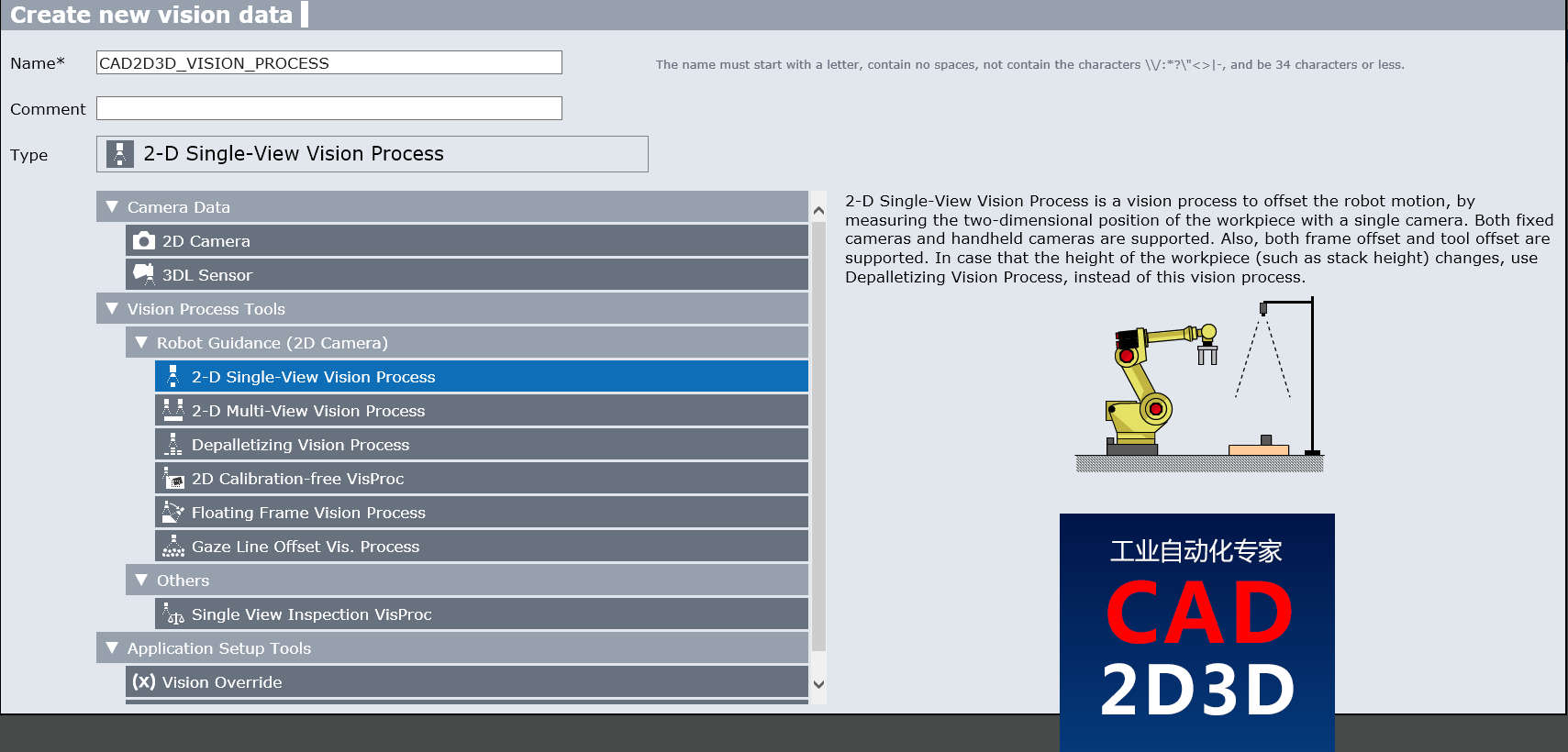
2-D Single-View Vision Process(二维单视图视觉处理)是一种视觉处理,可通过使用单个摄像头测量工件的二维位置来补偿机器人的运动。 固定摄像机和手持摄像机均受支持。 此外,还支持坐标偏移和刀具偏移。 如果工件的高度(例如堆叠高度)发生变化,请使用“卸垛视觉处理”,而不是该视觉处理。
2-D Single-View Vision Process is a vision process to offset the robot motion, by measuring the two-dimensional position of the workpiece with a single camera. Both fixed cameras and handheld cameras are supported. Also, both frame offset and tool offset are supported. In case that the height of the workpiece (such as stack height) changes, use Depalletizing Vision Process, instead of this vision process.
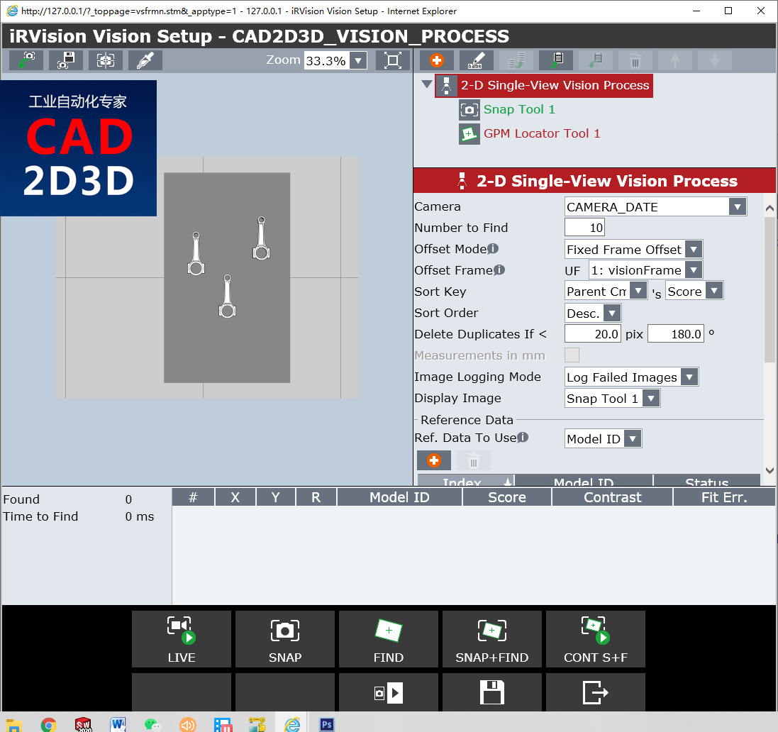
5.1 视觉处理工具设置(Vision Process Tools)
- Camera:选择相机
- Number to Find:查找数量
- Offset Mode:偏移模式
- Offset Frame:偏移坐标系
- Sort Key:排序字段
- Sort Order:排序方式,升级还是降级
- Delete Duplicates if < :删除重复内容
- Images logging Mode:图像日志模式
- Display Image:显示图像类型
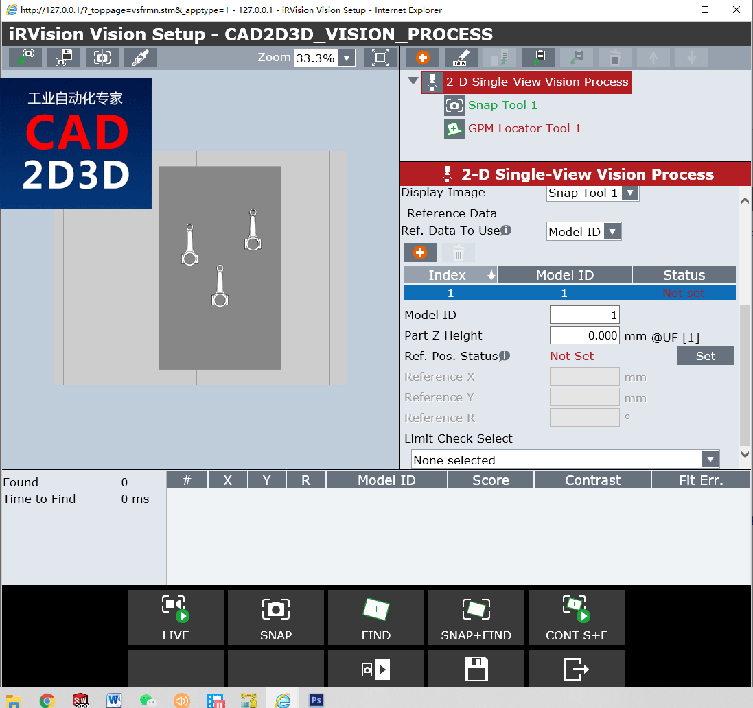
- Reference Data:引用数据
- Ref. Data to User:引用数据的使用
- Model ID:引用模型的编号ID
- Part Z Height:零件Z方向高度
- Ref. Pos. Status:引用位置状态
- Limit Check Select:范围变限检测
5.1.1 偏移模式(Offset Mode)
借助 Vision Get_Offset 指令,将偏移量存入视觉寄存器VR中。
The type of offset that is put into the VR, with the Vision Get_Offset TP instruction, is selected by the Offset Mode.
1)固定坐标系偏移 (Fixed Frame Offset)
固定坐标系偏移是最常用的偏移模式。 它允许用户在参考位置上示教工件,然后根据视觉偏移量,使机器人位置相对于该参考工件偏移。
The Fixed Frame Offset is the most commonly used offset mode. It allows the user to teach a workpiece at a reference position, and then have robot position offsets be relative to that reference workpiece.
在分析偏移时,使用固定坐标系偏移时,用户经常会犯一个常见的错误, 用户单独分析偏移量的X或Y分量是无效的, 由于是坐标系偏移,因此角度分量先于X和Y分量起作用。
In analyzing the offset, when using a Fixed Frame Offset, users often make a common mistake. It is invalid for users to analyze the X or Y component of the offset individually. Since it is a frame offset, the angle component comes into play before the X and Y component.
2)工具偏移(Tool Offset)
“工具偏置”模式下的偏置基于机器人的末端法兰盘。 刀具偏移量通常用于机器人握住工件,通过视觉找到工件位置,然后根据视觉偏移量,引导机器人将工件正确放置到指定位置。
The offset in the Tool Offset mode is based on the face plate of the robot. The tool offset is typically used in applications where the robot is holding the workpiece, finding its location in the gripper, and then using the vision offset to place it properly.
3)Found Position
Found Position 是基于偏移坐标系的工件的X,Y和Roll位置。Found Position 通常由具有高级应用程序的高级用户使用。 通过这种模式,可以将机器人的工具中心点(TCP)直接驱动到找到的工件的原点。 由于“Found Position”没有对应的机器人存储器,因此机器人无法直接移动到“Found Position”。 用户必须将X,Y和Roll值传送到位置寄存器中。
The Found Position is the X, Y and Roll position of the workpiece based on the offset frame. The Found Position is typically used by advanced users with advanced applications. With this mode the Tool Center Point (TCP) of the robot can be driven directly to the Origin of the found workpiece. Since the Found Position does not have the configuration string that a robot position contains, the robot cannot move directly to the Found Position. The user must transfer the X,Y, and Roll values into a position register.
5.1.2 Offset Frame
偏移坐标系包括用户坐标系和工具坐标系,视觉系统基于偏移坐标系计算偏移量。
The Offset Frame is the User Frame or Tool Frame that the vision offsets are calculated in.
有些视觉处理具有偏移模式,而有些则没有。 当“偏移模式”为“Fixed Frame Offset ”或“Found Position”时,“偏移坐标系”为用户坐标系。 当“偏移模式”为“工具偏移”时,“偏移坐标系”为“工具坐标系”。 如果视觉处理类型没有偏移模式,则偏移坐标系为用户坐标系。
Some vision processes have an Offset Mode and some do not. When the Offset Mode is Fixed Frame Offset or Found Position, the Offset Frame is a User Frame. When the Offset Mode is Tool Offset, then the Offset Frame is a Tool Frame. If the vision process type does not have an Offset Mode then the Offset Frame is a User Frame.
参考数据中的零件高度Z是从偏移坐标系中测量的。 只有当偏移坐标系示教到放置工件的工作台表面时,Z才等于零件高度或厚度。
The Part Z Height in the Reference Data is measured from the Offset Frame. The Part Z Height is the height or thickness of the workpiece if, and only if, the Offset Frame is taught to the surface that the wokrpiece is sitting on.
对于2D视觉应用,零件必须在偏移坐标系的XY平面内运动。
For 2D applications the workpieces must move in the X/Y plane of the offset frame.
根据示教器程序中的视觉偏移量,要偏移的机器人位置必须是在Offset Frame参数中指定的坐标系。
The robot positions to be offset, by the vision offset in the Teach Pendant Program, must be in the Frame specified by the Offset Frame.
5.1.3 可使用的参考数据(Reference Data To Use)
There are two types of reference data, Static and Model ID.
1)静态(Static)
静态是当所有找到的工件都使用相同的参考位置时要使用的参考数据模式。 这是一种常用模式,尤其是在所有工件都具有相同的Z部件高度的情况下。
Static is the reference data mode to use when all found workpieces are supposed to use the same reference positions. This is a common mode, especially if all the workpieces have the same Part Z Height.
2)Model ID
Model ID是当不同工件需要不同参考位置时要使用的参考数据。 如果不同的工件具有不同的Model ID,则可以使用该参考模式。 Model ID用于区分视觉过程中的不同工件。 具有不同Model ID的工件需要使用不同的参考数据,尤其是当它们具有不同的Z部件高度时。
Model ID is the reference data to use when different workpieces require different reference positions. If different workpieces have different Model IDs then this reference mode can be used. Model IDs are used to differentiate between different workpieces within a vision process. Workpieces with different Model IDs need to use different reference data, especially if they have different Part Z Heights.
5.1.4 参考位置状态(Reference Position Status)
除非偏移模式为 Found Position,否则必须设置参考位置。 处于参考位置的工件是机器人的示教位置。
The reference position must be SET unless the Offset Mode is Found Position. The workpiece, in the reference position, is the workpiece to which the robot handling positions are initailly taught.
要设置参考位置,请将工件放在视野内。 按SNAP + FIND, 验证是否在结果列表中以最高分数正确找到了合适的工件。 如果所需的工件不在结果列表中的第一位,则阻塞其他工件或暂时在“Locator tool”工具中修改搜索窗口,然后再次单击SNAP + FIND。 按SET键将找到的工件设置为参考工件。
To SET the reference position place a workpiece in the field of view. Press SNAP+FIND. Verify that the proper workpiece was properly found with the highest score in the results list. If the desired workpiece is not first in the results list, obstruct the other workpieces or temporarily modify the search window in the Locator tool, and SNAP+FIND again. Press SET to set the found workpiece as the reference workpiece.
设置参考位置后,根据视觉偏移量引导机器人到指定位置。 当工件处于参考位置时,视觉偏移将全部接近零。
Once the Reference Position has been set, teach the robot handling positions with the vision offsets. While the workpiece is at the reference position, the vision offset will all be near zero.
用户常用的技巧是先示教机器人位置来设置参考位置,将机器人移开,而不移动工件。
A common trick users do is to teach the robot handling positions first, move the robot out of the way, and without moving the workpiece set the reference position.
5.2 捕捉工具设置(Snap Tool)
- Snap Window:捕捉窗口
- Resolution Reduction:像素降低
- Image Size:图像尺寸
- Exposure Mode:曝光模式
- Exposure Time:曝光时间
- Multi Exposures:多重曝光
- LET Type:LED光源类型
- Image Display Mode:图像显示模式
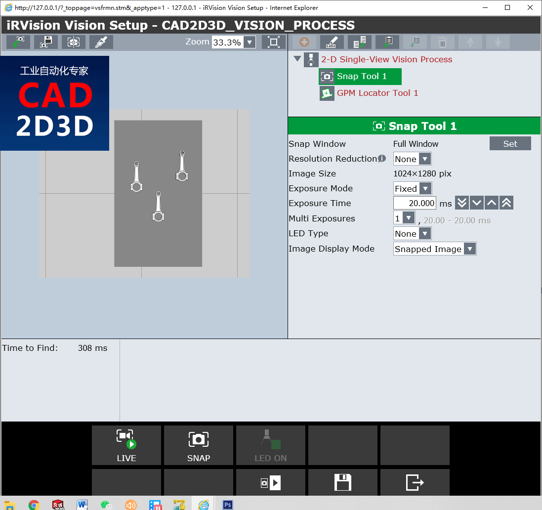
5.2.1 降低分辨率(Resolution Reduction)
通过将像素的正方形“ bin”组合为一个像素来降低图像分辨率。 对于2X的缩小,缩小图像中的每个像素都是根据原始图像中2X2像素的像素计算出来的,因此缩小图像的像素数是原来的1/4。 3倍和4倍的缩小级别使用3X3和4X4格,并进一步缩小图像尺寸。
The image resolution is reduced by combining square "bins" of pixels into one pixel. For a reduction of 2X, every pixel in the reduced image is computed from a 2x2 bin of pixels in the original image, so the reduced image has one 1/4 as many pixels. Reduction levels of 3X and 4X use 3x3 and 4x4 bins and reduce the image size even more.
分辨率降低可用于减少视觉处理时间,但会降低精度。许多视觉应用对精度要求不高,可以接受降低2倍X或更低精度。
Resolution reduction can be used to reduce vision processing time at the expense of precision. Many vision applications can be done with acceptable accuracy with a reduction of 2X or more.
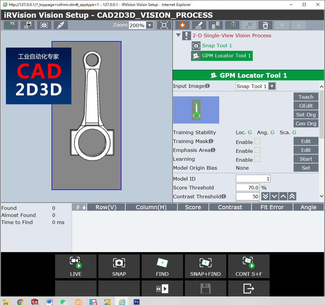
5.3 GMP Locator Tool 参数设置
- Input Image:输入图像
- Training Stability:训练稳定性
- Training Mask:遮罩
- Emphais Area:重点区域
- Learning:学习
- Model Origin Bias:模型原点偏差
- Model ID:模型ID
- Score Threshold:分数阈值
- Contrast Threshold:对比度阈值
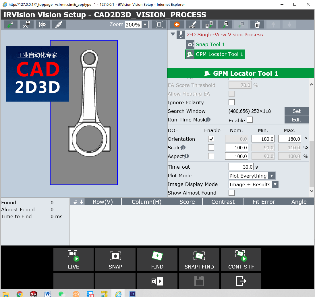
- Ignore Polarity:忽略极性
- Search Window:搜索窗口
- Run-Time Mask:运行遮罩
- DOF:自由度
- Orientation:朝向
- Scale:比例缩放
- Aspect:单项比例缩放
- Time-out:超时
- Plot Mode:绘图模式
- Image Display Mode:图像显示模式
- Show Aimost Found:显示最符合要求的
5.3.1 输入图象(Input Image)
输入图象就是当前工具使用的图象来源。
The Input Image is the source for the image used by the current tool.
输入图像的来源可以来自捕捉工具,图像滤镜工具,颜色分量工具,颜色提取工具或平面场工具。
The source for the input image can come from a snap tool, image filter tool, color component tool, color extraction tool, or a flat field tool.
视觉过程可能具有多个捕捉工具。 不同的命令工具可以在同一视觉过程中使用不同的捕捉工具。
A vision process may have multiple snap tools. Different command tools can use different snap tools in the same vision process.
5.3.2 蒙版遮罩训练器(Training Mask)
Training Mask 允许用户手动去除模型上不需要的边线,当一个模型被训练选中(Train)后,模型上所有的边线都会被统计进来,这里面有我们不需要的边线。
The Training Mask allows users to manually remove unwanted edges from the trained model. When a model is trained, all the edges within the trained area are counted as edges for the model. Many of these edges may be unwanted edges.
您可以通过使用绘图工具使用红色遮罩在所有不需要的绿色边缘上着色来选择要遮罩的区域。 例如,您可以选择对所有由于背景眩光,阴影或不必要的功能而导致的边缘进行遮罩掩盖。 去除不可靠的边缘会提高GPM定位器的得分。 遮蔽边缘时,可以使用图像缩放微调遮罩。
You can choose the areas to mask by using the drawing tools to color over all unwanted green edges with the red mask. For example, you may choose to color over all edges that are the result of glare, or shadows, or unwanted features in the background. Removal of unreliable edges will improve the score of the GPM Locator. When masking edges, use the image zoom to finely tune the mask.
可通过“Runtime ”查看运行效果,注意红色显示的边缘,并使用“Training Mask”将其手动从考虑中删除。
While running production, watch the Vision Runtime screen and note any edges consistently shown in red, and manually remove them from consideration, using the Training Mask.
5.3.3 重点领域(Emphasis Area)
重点区域用于增加模型中特定边线的重要性。
The Emphasis Area is used to add importance to specific edges in the trained model.
使用绘图工具覆盖住重点区域的边线
Using the drawing tools cover over all the edges to be emphasized with blue.
重点区域是区分两个相似工件且仅有微小差异的重要工具。
The Emphasis Area is a valuable tool to differentiate between two like workpieces with only subtle differences.
EA得分阈值或重点区域得分阈值用于确定需要多少百分比的强调边缘,才能确定是否正确的找到了工件。
The EA Score Threshold or Emphasis Area Score Threshold is used to determine what percentage of the emphasized edges are required to determine if a workpiece is found.
5.3.4 对比度阈值(Contrast Threshold)
对比度是两个相邻像素之间的灰度差异。 图像中的每个像素的灰度值介于零(黑色)和255(白色)之间。设定对比度阈值是为了寻找模型边缘,当相邻两个像素的对比值差值超过设定的阈值时,就确定为边缘点。
Contrast is the grayscale difference between two neighboring pixels. Each pixel in an image has a grayscale value between zero (black) and 255 (white). The Contrast Threshold is the minimum contrast difference between two neighboring pixels in order to create an edge.
经过GPM定位器训练的模型由边缘线组成。 如果两个像素之间的对比度大于“对比度阈值”,则认为在两个像素之间存在边缘。 工件边缘和背景之间的对比度越高,效果越好。 工件边缘和背景之间的对比度低会导致很难确定边缘。
The GPM Locators trained model is made up of edges. If the contrast between two pixels is greater than the Contrast Threshold, then an edge is considered to exist between the two pixels. The higher the contrast, between the edges of the workpiece and the background, the better. A low contrast between the workpieces edges and the background can lead to poor finds.
如果对比度阈值设置得太高,则将找不到部分或全部工件边缘。 如果对比度阈值设置得太低,则可能会错误地发现工件。
If the Contrast Threshold it set too high, then some, or all, of the workpieces edges will not be found. If the Contrast Threshold is set too low, then there is the potential for false finds of the workpiece.
对比度阈值越低,在图像中会发现更多的潜在边缘。 GPM定位器的查找时间将随着图像中边缘数量的增加而增加。 尽可能设置图像的照明和光学器件,以使工件和背景之间的对比度高,并且对比度阈值应设置得尽可能高。
The lower the Contrast Threshold, the more potential edges will be found in the image. The find-time of the GPM Locator will increase as the number of edges in the image increases. Whenever possible, set up the lighting and optics of the image so that the contrast between the workpiece and background is high and the Contrast Threshold is set as high as possible.
最低对比度阈值为1。可靠的视觉应用通常需要高对比度阈值。
The minimum Contrast Threshold is 1. A threshold that low is likely not going to lead to a robust vision application.
5.3.5 弹性(Elasticity)
弹性是允许偏离边缘线的像素数量,类似尺寸公差的概念。
The Elasticity is the amount of pixels that a found edge is allowed to deviate from the original location of the trained edge.
由于找到的对象并不一定总是与训练后的模型完全匹配,因此需要弹性以允许存在任何小的差异。 通常1.5像素的默认值太低,因此用户需要调整该值。
Since found objects do not always match the trained model perfectly, elasticity is necessary to allow for any small differences. Often the default of 1.5 pixels is too low and so the user needs to adjust this value.
提高弹性通常会增加找到的工件的分数。 在许多应用中,值为3或最大值5是可以接受的。
Raising the Elasticity will often increase the score of the found workpieces. In many applications a value of 3 or the max of 5, is acceptable.
但是请记住,如果弹性太高,则可能导致错误或错误的发现。 另一方面,如果弹性太低,将导致得分较低或找不到有效的工件。
Keep in mind, however, that if the Elasticity is too high, it might lead to false or incorrect finds. On the other hand, if the Elasticity is too low, it will lead to low scores or failures to find valid workpieces.
5.3.6 运行遮罩(Run-Time Mask)
运行遮罩用于掩盖搜索窗口中的区域。 该工具不会搜索在遮罩区域内经过训练的模型。
The Run-Time Mask is used to mask out areas within the search window. The tool will not search for the trained model within the masked areas. The Run-Time Mask works like a search window, except it is not limited to a rectangular shape like the the search window.
遮住不需要的区域可能会缩短查找时间,并减少错误查找的可能性。
Masking out unwanted areas may improve find times and reduce the potential for false finds.
5.3.7 缩放比例自由度(Scale Degree of Freedom)
缩放比例是找到的工件与经过训练的模型相比的尺寸。
The Scale is the size of the found workpiece compared to the trained model.
找到的工件的比例有两种变化方式。 如果工件的尺寸与受训工件的尺寸不同,则比例会变化。 或者,如果从相机到工件的距离发生变化,则与训练模型时的距离相比,比例会发生变化。
The scale of a found workpiece can vary in two ways. If the workpiece changes in size from the size of the trained workpiece, then the scale will vary. Or if the distance from the camera to the workpieces changes, compared to the distance when the model was trained, then the scale will vary.
如果启用了“缩放”,则GPM定位器将在“最小”与“最大”之间的范围内查找工件。 如果未启用比例,则GPM将仅以训练模型时确定的比例(称为标称)查找到工件。
If the Scale is enabled, then the GPM Locator will find workpieces within the range between the Min. and Max. If the Scale is not enabled, then the GPM will only find workpieces at the scale determined when the model was trained called the Nominal.
启用“缩放”,尤其是在较大范围内,将大大增加查找工件的处理时间,并增加错误查找的可能性。
Enabling the Scale, especially with a large range, will drastically increase the processing time to find the workpieces and increase the possibility of false finds.
5.3.8 宽高自由度(Aspect Degree of Freedom)
宽高自由度是与训练后的模型相比,工件的尺寸在一个方向上的变化。 例如,倾斜的方形工件(最初训练模型时未倾斜)在相机中可能会显示为矩形,或者在类似情况下,可能会发现一个圆形为椭圆形。 在这两种情况下,纵横两个方向都发生了变化。
Aspect is the change in size of the found workpiece in one direction compared to the trained model. For example, a tilted square workpiece (which was not tilted when the model was originally trained) might appear to the camera as a rectangle, or, under similar circumstances, a circle might be found as an ellipse. In either case, there has been an aspect change.
自由度(DOF)允许您指定宽高比。 如果宽高比值大于或小于指定值,将找不到模型。
The Degrees of Freedom (DOF) allows you to specify the range for aspect. If the aspect value is greater, or less than, the specified values, the model will not be found.
启用宽高比,特别是在较大范围内,将大大增加查找工件所需的处理时间,并增加错误查找的可能性。
Enabling the Aspect, especially with a large range, will drastically increase the processing time required to find the workpieces and increase the possibility of false finds.
6. 视频实操演示
视频观看方式:微信扫描下方二维码直接观看:

7 FANUC ROBOGUIDE iRVision 程序代码
	URFAME_NUM=1
	UTOOL_NUM=1

	LBL[1]
	PR[1:HOME] 2000mm/sec FINE
	VISION RUN_FIND "VISIONDATA"
	VISION GET_NFOUND "VISIONDATA" R[10]
	R[20]=R[10]
	IF R[10]=0, JMP LBL[100]

	LBL[10]

	VISION GET_OFFSET "VISIONDATA" VR[R[10]] JMP LBL[100]
	R[10]=R[10]-1
	IF R[10]<>0, JMP LBL[10]

	LBL[50]

	L PR[3:PART_OFFSET] 3000mm/sec FINE Offset, PR[2:Z_OFFSET] VOFFSET, VR[R[20]]
	L PR[3:PART_OFFSET] 3000mm/sec FINE VOFFSET, VR[R[20]]
	CALL PICK_SIM
	L PR[3:PART_OFFSET] 3000mm/sec FINE Offset, PR[2:Z_OFFSET] VOFFSET, VR[R[20]]
	L PR[1:HOME] 3000mm/sec FINE
	CALL DROP_SIM
	R[20]=R[20]-1
	IF R[20]<>0, JMP LBL[50]

	LBL[100]
转载请注明:
文章作者: 尚延伟 原文链接:https://www.cad2d3d.com/post-1442.html
留言说明:
如对本文有疑问,可关注微信公众号 喜爱的CAD 直接留言即可。手机扫描下方二维码直接关注 喜爱的CAD。

也可以直接发邮件给我,我的邮箱18036678070@cad2d3d.com


可能感兴趣的文章
 落魄的凤凰不如鸡,一级建造师落寞了,24年的证书补助还没给,就差项目经理跪下了
 挡圈卡簧种类及对应的实物图,挡圈卡簧名称中英文对照
 笑掉大牙!电气软件这么落后吗?必须要用25年前的Windows NT/2000/XP才行?
 日本 NITTA 机器人柔性夹爪!如人手般温柔的抓住!可搬运最大重量1380g
- 运动粘度、动力粘度的定义及单位换算,动力粘度与运动粘度相互换算公式
- 304不锈钢设备我都不敢承诺使用寿命20年,为啥钢筋混泥土的房子开发商却敢承诺寿命50年?
- ISO 5208 金属阀门泄漏率的定义,Rate A 无目视可检测到的泄露,泄露量单位 mm³/s和drops/s
- 顶装(上装)球阀、侧装球阀的区别,顶装、侧装球阀选型原则
- 法国T.EN (TECHNIP ENERGIES)公司官网,专注于LNG装卸臂、大臂、等能源转运产品
- 压力容器和工业金属管道壁厚的计算厚度公式异同点
更多最新发布: 工业相机视觉系统
-
视觉应用案例!采用HALCON组件模型匹配算法识别槽车法兰位置
-
FANUC iRVision 视觉学习——相机校准、视觉数据、用户坐标系和工具坐标系
-
 发那科机器人(FANUC)视觉(iRVision)操作说明书pdf免费下载,详细介绍如何利用视觉实现机器人自动抓取工件
-
3D视觉专用名词概念解释,深度图、点云图、IR图、RGB图像
-
发那科FANUC机器人视觉软件 iRVision 使用方法和步骤详述,相机设置、标定方法、视觉处理工具等各项参数含义解释
-
 工业相机视觉系统学习—彩色相机的效果和预处理
-
三维视觉系统(3D视觉)的重复精度(±3σ)是什么意思,重复定位精度是如何计算出来的?
-
高温热态尺寸在线测量,3D视觉识别建模,锻造工件尺寸自动测量
 本站所有资源一键获取,含3D模型、设计软件和案例视频等
 支付宝现金红包,又疯狂“大面积”送钱了!人均 1-20 元 (无套路/每天能领)
 AutoCAD 2025 破解版+注册机 安装程序免费下载,附下载地址及安装教程
 SolidWorks 2024 SP2.0 破解版免费下载及安装教程
 发那科机器人 FANUC 离线编程 动画仿真模拟软件 ROBOGUIDE V9 免费下载